Oct 20, 2026
Submersible UV Lamp Selection Guide for Water Tanks and Industrial Treatment
Learn how to select a submersible UV lamp assembly by water conditions, quartz sleeve, waterproof seals, cable, ballast, mounting and maintenance needs.
Submersible UV lamp assemblies place the germicidal source directly inside a tank, channel or treatment chamber instead of relying on a separate closed reactor. This arrangement can simplify retrofits and bring UV-C closer to the treatment zone, but it also creates demanding requirements for waterproof sealing, quartz protection, cable routing, electrical safety and maintenance access.
This guide helps overseas OEM buyers, water-treatment companies and equipment integrators specify a submersible UV lamp assembly for process tanks, storage vessels, aquaculture equipment, wastewater applications and industrial water systems.
What Is a Submersible UV Lamp Assembly?
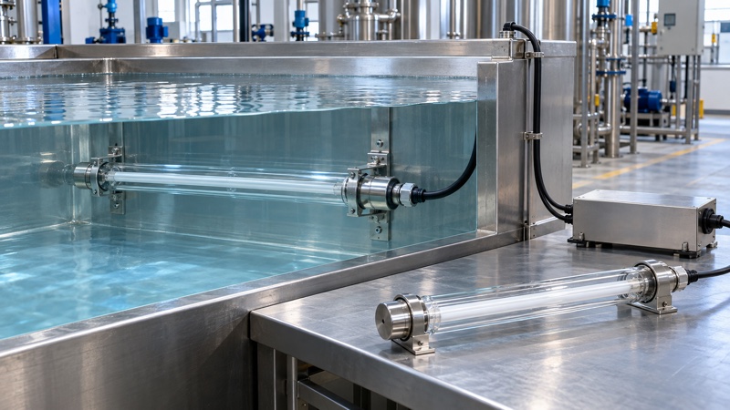
A submersible UV product is normally more than a bare lamp. The UV-C lamp is protected from water by a quartz sleeve or sealed quartz housing. Waterproof end fittings, O-rings, cable glands and a suitable cable form the electrical and mechanical connection. The electronic ballast and control components are usually installed in a dry, protected location outside the water.
Buyers should therefore request a complete assembly specification, not only a wattage. The UV germicidal lamp tube, quartz sleeve, sealing structure, cable and UV electronic ballast must be matched as one system.
Where Submersible UV Lamps Are Used
Typical projects include recirculating water tanks, process-water reservoirs, wastewater channels, cooling-water systems, aquaculture tanks, food and beverage equipment, water features and OEM treatment modules. The same assembly is not suitable for every application because water chemistry, temperature, tank material, cleaning method and required disinfection performance vary.
For new projects, define whether the goal is microbial control in stored water, treatment of flowing water, surface control inside a vessel or support for another treatment process. This determines the required lamp arrangement, exposure zone and control strategy.
Start With the Water and Process Conditions
UV-C performance depends on more than lamp power. The water must allow useful UV energy to reach the target area. Color, suspended solids, turbidity, dissolved material and fouling can reduce transmission or create shaded regions. A tank with clear water may need a very different layout from an industrial vessel containing particles or process residue.
Prepare the following process information before requesting a quotation:
- Tank dimensions, working volume and water depth
- Static, recirculating or continuous-flow operation
- Water temperature range
- Water quality, turbidity and fouling tendency
- Target microorganism or treatment objective
- Required operating hours and switching cycle
- Cleaning chemicals and cleaning frequency
- Tank material and available mounting points
Where the process objective requires a verified UV dose, system-level engineering and validation are necessary. Lamp wattage alone cannot establish dose in an open or mixed tank.
Select the Lamp Type and Power
Low-pressure UV-C lamps are commonly used where compact size and efficient germicidal output are needed. Higher-power or amalgam lamp designs may be considered for larger treatment loads, but thermal conditions, ballast compatibility and sleeve dimensions become especially important.
Compare lamp power, arc length, tube diameter, base type, operating current and expected temperature. The article on UV germicidal lamp tube diameter explains how mechanical size affects sleeve clearance and holders. For higher-output projects, review the BIOSUN amalgam UV lamp range and validate the assembly under actual water conditions.
Quartz Sleeve and Housing Design
The quartz barrier protects the electrical lamp from water while transmitting UV-C. It must have the correct material, wall thickness, diameter, length and end structure. A closed-end sleeve can reduce the number of underwater electrical interfaces, while other assemblies use sealed fittings at both ends. The final design depends on installation and service access.
Review UV quartz sleeve options together with the lamp drawing. The lamp must fit without contact, and the sleeve must tolerate handling, operating temperature and the intended cleaning process.
Plan for sleeve fouling
Mineral deposits, biofilm and process residue can lower transmission. A lamp may remain illuminated while delivered UV-C declines. Design enough access to remove or clean the sleeve, and establish a documented inspection interval. The quartz sleeve maintenance guide covers cleaning and replacement indicators.
Waterproof Seals, End Caps and Cable Glands
The sealing system is a critical part of a submersible assembly. O-rings, compression parts, end caps and cable glands must be compatible with the water, temperature and cleaning chemicals. Seal materials should be specified rather than accepted as an unknown standard part.
Ask the supplier for an assembly drawing that shows sealing locations, compression method, cable entry and service procedure. If the sleeve can be replaced, define how seals are renewed and how technicians avoid over-tightening the quartz. Relevant UV lamp accessories should be included in the spare-parts plan.
Do not rely only on a connector description
Terms such as waterproof connector are not enough for project approval. The complete installed assembly, cable gland, mating connector, enclosure and cable routing must meet the equipment’s environmental requirements. Protection can be lost if a connector is unmated underwater, assembled incorrectly or used with the wrong cable diameter.
Cable Length and Routing
Cable length should be confirmed with the ballast supplier because long output cables can affect starting and electrical behavior. Do not extend a lamp cable in the field without approval. Specify the required length, conductor arrangement, insulation, connector, bend radius and strain relief during sample development.
Route the cable away from sharp edges, moving equipment and hot surfaces. Provide mechanical support so cable weight does not pull on the lamp seal. A drip path and protected dry-side connection reduce the chance of water traveling toward the ballast or control enclosure.
Keep the Ballast and Controls Protected
Unless the complete product is specifically designed and certified for immersion, the ballast and controller should remain outside the tank in a suitable dry enclosure. Confirm input voltage, frequency, lamp output, startup method, fault feedback and cable-length limits.
The lamp and ballast must be electrically compatible even if the connector fits. Use the UV lamp operating-current and ballast compatibility guide to compare the required data, and review filament preheating and ballast startup when the equipment switches frequently.
Installation Position and Tank Coverage
The assembly may be mounted horizontally, vertically or at an engineered angle. Position affects water mixing, air-bubble accumulation, sediment exposure, maintenance access and the illuminated zone. Mounting brackets must support the sleeve without creating stress points.
Avoid locations where the assembly can be struck by tools, tank internals or moving equipment. Keep enough clearance for sleeve removal. In tanks with poor circulation, multiple lamps or a recirculation loop may be more reliable than increasing the power of one lamp.
Prevent shadowed treatment zones
Baffles, pipes, supports and suspended solids can block UV-C. Use tank drawings or a representative prototype to evaluate coverage. If the process relies on water circulation past the lamp, verify the flow pattern instead of assuming that the full tank receives equal exposure.
Temperature and Operating Environment
Lamp output and electrical behavior can change with temperature. Submersion may cool the sleeve, while warm process water can create different conditions. The selected lamp should be validated across the intended water-temperature range and operating cycle.
For systems using higher-power lamps, thermal management is part of the reactor design. BIOSUN’s amalgam UV lamp temperature-management guide explains why water flow, sleeve conditions and ballast matching must be considered together.
Safety and Interlock Requirements
UV-C can harm eyes and skin. The installation should prevent direct exposure during operation and service. A tank cover, opaque shielding, access interlock and clear maintenance procedure may be required depending on the equipment. The lamp should switch off before a worker can view or remove the assembly.
Electrical protection must be designed by qualified personnel for the local installation. Grounding, leakage protection, cable glands, enclosure selection and disconnect procedures should be included in the equipment design. Never energize a damaged or leaking assembly.
Monitoring and Alarm Design
At minimum, the controller should indicate lamp or ballast fault where the application requires service notification. More advanced systems may use runtime counters, individual lamp feedback or UV intensity sensors.
A sensor reading can be influenced by sleeve fouling, water quality, geometry and temperature, so alarm thresholds need validation. The UV lamp monitoring and sensor selection guide explains the difference between electrical status and optical intensity monitoring.
OEM Sample Validation Checklist
Mechanical inspection
- Confirm overall length, sleeve diameter and mounting dimensions
- Check bracket support, cable routing and maintenance clearance
- Verify that the quartz is not under side load or point pressure
Seal and immersion testing
- Test the complete assembled unit under defined immersion conditions
- Inspect seals, cable glands and connectors before and after the test
- Repeat after assembly and service operations where relevant
Electrical operation
- Verify startup, stable current, ballast temperature and fault response
- Test with the approved cable length and production connector
- Confirm operation across the specified supply and water-temperature range
Application performance
- Evaluate the real tank geometry, water quality and circulation pattern
- Confirm alarm logic and maintenance intervals
- Document the approved lamp, sleeve, seal, cable and ballast combination
Use the UV lamp sample approval guide to keep engineering and purchasing records aligned before mass production.
Maintenance and Spare Parts
Maintenance should include safe isolation, sleeve cleaning, seal inspection, cable and gland inspection, lamp-hour review and functional alarm testing. Replace cracked, clouded or deeply scratched quartz components. Renew seals according to the service procedure instead of reusing compressed parts indefinitely.
Keep matched spare lamps, sleeves, O-rings, end fittings and ballasts available for critical systems. The UV lamp spare-parts stocking guide can help distributors and service teams plan replacement kits.
Common Purchasing Mistakes
- Ordering only by lamp wattage without defining the waterproof assembly
- Assuming a standard quartz sleeve fits every lamp and seal design
- Extending the lamp cable without ballast approval
- Placing the ballast in a wet area without a suitable enclosure
- Ignoring water quality, fouling and tank circulation
- Providing no safe way to remove and clean the sleeve
- Using the same material specification for incompatible chemicals
- Approving one dry bench test without immersion and application testing
RFQ Information for a Submersible UV Project
For faster technical review, send BIOSUN:
- Application and treatment objective
- Tank drawing, dimensions, working volume and water depth
- Water quality and temperature range
- Flow or recirculation details
- Required lamp quantity, power and operating schedule
- Preferred mounting position and available service space
- Required cable length, connector and control interface
- Cleaning chemicals and seal-material requirements
- Destination country, input voltage and project quantity
FAQ About Submersible UV Lamps
Can a standard UV lamp be placed directly in water?
No. The electrical lamp needs a properly designed quartz sleeve or sealed housing, waterproof fittings and an approved electrical system. A bare lamp should not contact water.
Can the ballast also be submerged?
Only if the complete ballast product is specifically designed and approved for that environment. In most assemblies, the ballast is mounted outside the tank in a protected dry enclosure.
How often should the quartz sleeve be cleaned?
The interval depends on water quality, temperature, fouling and required performance. Inspect early in the project, record deposit buildup and establish a maintenance interval from actual conditions.
Is one high-power lamp better than several smaller lamps?
Not automatically. Coverage, mixing, shadowing, service access and redundancy all matter. Compare layouts using the real tank geometry and treatment objective.
Can a submersible UV assembly be customized?
Yes. Lamp length and power, quartz sleeve, mounting brackets, cable length, connector, seal materials and ballast interface can be developed for an OEM project, subject to sample validation.
Develop a Submersible UV Lamp Assembly With BIOSUN
BIOSUN supports OEM and replacement projects with UV-C lamps, quartz sleeves, electronic ballasts, accessories and customized assembly matching. The best result comes from reviewing the lamp, waterproof structure, tank geometry and control system together.
See the BIOSUN OEM and ODM service or send your tank drawing and operating conditions through the BIOSUN contact page.
Need a UV product quotation?
Send the model, drawing, application and expected quantity. BIOSUN will review the matching details and reply by email.
Send Inquiry