Oct 16, 2026
UV Lamp Monitoring and Sensor Selection Guide for OEM Disinfection Systems
Learn how to select UV lamp status monitoring, intensity sensors, alarm thresholds and maintenance logic for OEM disinfection systems.
A UV disinfection system should do more than switch a lamp on. For OEM equipment, water-treatment reactors and air-disinfection products, the control system needs a practical way to identify lamp failure, declining performance and conditions that may reduce delivered UV energy. The right monitoring method depends on what the equipment must prove, how it will be maintained and how the alarm will be used.
This guide helps overseas OEM buyers compare lamp-current monitoring, UV intensity sensors and related control functions before approving a UV lamp system.
What Should a UV Monitoring System Tell You?
Monitoring can answer several different questions. Is the ballast energized? Is electrical current flowing through the lamp? Is UV-C reaching a sensor location? Has the quartz surface become dirty? Is the process still within the equipment’s validated operating range?
No single signal answers all of these questions. A buyer should first define the required decision, then select the sensor and alarm logic. When sourcing UV germicidal lamp tubes, include the intended monitoring method in the technical request so the lamp, ballast, reactor and controller can be reviewed together.
Lamp Status Monitoring vs UV Intensity Monitoring
Electrical lamp status
Lamp-status monitoring usually relies on information from the ballast or an external current-sensing method. It can indicate whether the lamp circuit is operating, whether a fault has been detected or whether the ballast has entered protection. This is useful for basic fault detection and service alerts.
However, electrical operation does not directly prove that sufficient UV-C reaches the treatment zone. A lamp can remain electrically active while its useful output changes because of aging, temperature, contamination or optical obstruction.
UV intensity measurement
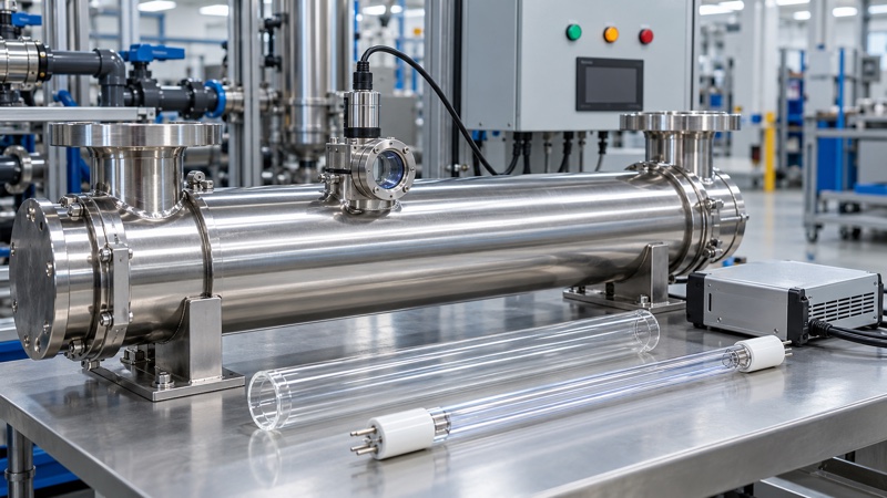
A UV sensor responds to radiation at its installed location. In a water reactor, it may view the lamp through a dedicated quartz window. In an air or surface system, it may be positioned to monitor a representative part of the treatment field. The reading reflects the combined effect of the lamp, optical path, sensor window, geometry and environmental conditions.
Intensity monitoring can provide a more direct process-related signal, but it requires careful placement, calibration, cleaning and interpretation. It should not be treated as a universal dose measurement unless the complete system has been designed and validated for that purpose.
Choose the Monitoring Level for the Application
A compact appliance may only need lamp-on and lamp-fault feedback. A commercial water sterilizer may require a dedicated UV sensor, low-intensity alarm and shutdown or bypass logic. A multi-lamp industrial system may need individual lamp status plus a process-level intensity signal.
| Monitoring level | Typical signal | What it can support |
|---|---|---|
| Basic | Power, ballast fault or lamp current | Lamp-on indication and basic service alarm |
| Intermediate | Individual lamp status, runtime and switching count | Preventive maintenance and fault identification |
| Process-oriented | UV intensity plus flow, temperature or other process inputs | Validated alarm logic and operating decisions |
The selected level should match the equipment’s risk assessment, customer expectations and validation plan. Avoid adding a sensor only because a competitor uses one; define what action the system will take when the signal changes.
Match the Sensor to the Lamp and Wavelength
UV sensors have different spectral responses. A sensor intended for conventional germicidal UV-C monitoring may not respond appropriately to every lamp technology or wavelength. Confirm the lamp type, sensor response range, filter characteristics and expected signal level with the suppliers.
This is especially important when comparing standard low-pressure lamps, ozone-generating lamps, amalgam lamps or other specialized sources. Buyers should not assume that one sensor can be transferred between all products without revalidation. For higher-output water-treatment projects, review the amalgam UV lamp range together with the sensor’s operating range and reactor geometry.
Sensor Placement and Viewing Geometry
A sensor reading is strongly influenced by where the sensor is installed and what it can see. Distance from the lamp, viewing angle, reflector shape, reactor wall, water path and nearby lamps can all affect the signal.
Water-treatment reactors
In a reactor, the sensor often views the lamp through a quartz window or optical port. The port must remain sealed and must not create a maintenance problem. The position should be defined on the approved reactor drawing so production units use the same geometry.
The lamp may also operate inside a quartz sleeve. Sleeve transmission, scaling and condensation can change the amount of UV reaching the sensor, so lamp monitoring and sleeve maintenance should be planned together.
Air and surface systems
In ducts, appliances and cabinets, the sensor should represent the treatment zone without being shadowed by supports, wiring or guards. Airflow, dust and cleaning access should also be considered. A sensor that sees only a bright local reflection may not represent the wider irradiated area.
Account for Quartz Window Fouling
A declining sensor signal does not always mean the lamp has failed. Deposits on a quartz sleeve or sensor window can reduce transmission. In water applications, minerals, organic material and cleaning residue may affect the optical path. In air systems, dust or films can collect on exposed surfaces.
Design the assembly so the window can be inspected and cleaned. Document the cleaning method, acceptable condition and replacement criteria. BIOSUN’s article on quartz sleeve cleaning in UV water treatment explains why optical maintenance matters even when the lamp still appears to operate.
Use the Ballast Feedback Correctly
Many UV electronic ballasts can provide fault, lamp-status or control signals. The interface may be a relay contact, open-collector output, analog signal or digital communication, depending on the model.
Before connecting the ballast to the equipment controller, confirm signal type, voltage limits, logic state, isolation, response time and behavior during startup. A fault output may change state while the lamp is warming up, so the controller should distinguish normal startup from a true failure.
For systems with power adjustment, coordinate the sensor logic with the UV lamp dimming and power-control sequence. A lower sensor reading may be expected at reduced power and should not automatically trigger the same alarm used for a failed lamp.
Set Alarm Thresholds From Validation Data
An alarm threshold should not be copied from an unrelated system. Establish the baseline using the approved lamp, ballast, reactor, sensor, water quality or airflow, operating temperature and clean optical surfaces. Then test expected variation across multiple samples and operating conditions.
Useful alarm design questions include:
- What reading is expected after normal warm-up?
- How much sample-to-sample variation is acceptable?
- How does the signal change with temperature, flow or lamp power?
- What delay prevents false alarms during startup?
- Should a low reading create a warning, shutdown or service request?
- How will the system respond to a disconnected or failed sensor?
- Who is authorized to reset or recalibrate the alarm?
Keep warning and shutdown logic separate when the application benefits from early maintenance notice. Any threshold that controls process acceptance should be supported by system-level validation rather than by lamp specifications alone.
Commissioning Tests for UV Monitoring
Commissioning should verify the complete signal path from the lamp to the operator interface. The UV water sterilizer commissioning checklist provides a broader equipment-level framework.
Confirm installed components
Record the lamp model, ballast, sensor model, quartz window, controller software version and wiring revision. Check that the installed parts match the approved sample.
Verify startup behavior
Observe lamp ignition, warm-up, sensor response and alarm delays. Repeat the test under relevant cold and warm conditions if temperature affects the application.
Challenge the alarms
Use controlled test methods to verify lamp-fault, low-intensity, disconnected-sensor and other required conditions. Confirm the displayed message, relay response, shutdown logic and recovery procedure.
Record a clean baseline
After cleaning and stable operation, document the normal sensor reading or accepted range. This becomes a useful service reference, but it should only be compared with readings taken under equivalent operating conditions.
Maintenance and Recalibration Planning
A monitoring system needs its own maintenance plan. Sensor windows may require cleaning, cables and connectors need inspection, and the sensor may require periodic verification or recalibration according to its specification. Protect calibration settings from accidental changes.
Runtime counters can support lamp replacement planning, but operating hours alone do not describe every performance factor. Combine hours, sensor trend, sleeve condition, ballast status and application requirements. The UV lamp lifespan and replacement interval guide explains how these maintenance signals work together.
Common Monitoring Design Mistakes
- Using ballast power status as proof of adequate UV output
- Selecting a sensor without checking wavelength response
- Changing sensor position between prototypes and production
- Ignoring fouling on the sensor window or quartz sleeve
- Setting alarm thresholds before testing real operating variation
- Triggering false alarms during normal lamp warm-up or dimming
- Providing no way to detect a disconnected sensor
- Making the sensor impossible to inspect or clean
RFQ Checklist for an OEM Monitoring System
When requesting a lamp, ballast and monitoring solution, provide:
- Application: water, air, surface or appliance disinfection
- Lamp type, model, quantity and operating power
- Ballast model and required control interface
- Reactor or chamber drawing
- Sensor purpose: lamp status, intensity trend or process alarm
- Expected temperature, humidity, flow and cleaning conditions
- Controller input type and alarm outputs
- Required maintenance access and calibration plan
- Sample quantity and validation schedule
FAQ About UV Lamp Monitoring
Can a current sensor replace a UV intensity sensor?
Not when the system must monitor UV reaching the treatment area. Current sensing can confirm electrical operation, while an optical sensor responds to radiation at its location. The required function decides which signal is appropriate.
Why does the UV sensor reading fall while the lamp is still on?
Possible causes include lamp aging, temperature change, reduced lamp power, quartz fouling, sensor-window contamination, changed water quality, altered geometry or sensor drift. Inspect the complete system before replacing one component.
Should every UV water sterilizer have an intensity sensor?
The monitoring requirement depends on the equipment design, intended use, validation and customer specification. Basic products may use lamp-status monitoring, while higher-control applications may require intensity and process signals.
Can one alarm threshold be used for every lamp model?
No. Thresholds should be established for the approved lamp, ballast, sensor and system geometry under defined operating conditions.
Develop a Monitored UV System With BIOSUN
BIOSUN can support OEM buyers with UV lamp selection, ballast matching, quartz sleeves, accessories and sample preparation for monitored disinfection equipment. Share the application, reactor drawing, lamp model, control interface and required alarm behavior so the components can be reviewed as a system.
Review the BIOSUN OEM and ODM service or send your project information through the BIOSUN contact page.
Need a UV product quotation?
Send the model, drawing, application and expected quantity. BIOSUN will review the matching details and reply by email.
Send Inquiry