Sep 29, 2026
UV Lamp Dimming and Power Control Guide for OEM Disinfection Systems
A practical OEM guide to dimmable UV lamps, electronic ballast control, minimum power levels, warm-up logic and sample validation.
UV lamp dimming can help OEM equipment adapt output to changing airflow, water flow or operating schedules, but it is not achieved by connecting a standard lamp to an ordinary wall dimmer. The lamp, electronic ballast, control signal and monitoring logic must be designed and tested as one system. This guide explains the main decisions for buyers specifying dimmable UV germicidal lamp tubes in air and water disinfection equipment.
What UV lamp dimming actually controls
In a compatible system, the electronic ballast adjusts the electrical power delivered to the lamp within an approved range. The resulting UV output normally changes with lamp power, but the relationship may not be perfectly linear and can depend on lamp temperature, age and application conditions. OEMs should validate useful germicidal output at each operating level instead of assuming that a 50 percent control command always means exactly 50 percent UV output.
Dimming is different from switching banks of lamps on and off. Both methods can provide capacity control, but they create different electrical, thermal and maintenance behavior. The most suitable strategy depends on system size, required redundancy, operating hours and how quickly the process load changes.
Why OEM systems use variable UV power
Match treatment capacity to changing process load
A water system may experience varying flow or UV transmittance, while an air-treatment unit may run at several fan speeds. Variable lamp power can be part of a validated control strategy that responds to these changes without operating at maximum power continuously.
Reduce unnecessary energy use
When the process demand is lower, a verified reduced-power level may save energy and limit excess heat. Energy savings should be measured at the system input, including the UV electronic ballast, rather than estimated only from a controller percentage.
Avoid excessive start-stop cycling
Some applications use a stable low-power mode instead of repeatedly turning lamps off for short idle periods. Whether this is appropriate depends on the lamp and ballast design, minimum stable power, thermal conditions and safety logic. The control method must follow the component supplier’s approved operating limits.
Not every UV lamp and ballast is dimmable
A physically compatible lamp is not automatically suitable for power control. The ballast must support the exact lamp load and provide an approved control interface. Buyers should confirm lamp operating current, voltage, rated power, starting method and permissible power range. The UV lamp current and ballast compatibility guide lists the electrical data needed for this comparison.
Standard low-pressure lamps, high-output lamps and amalgam UV lamps can behave differently when power is reduced. Amalgam lamp output is particularly sensitive to thermal conditions, so the permitted dimming range should be tested in the intended sleeve, chamber and flow environment. Review the amalgam lamp temperature management guide when specifying a water-treatment system.
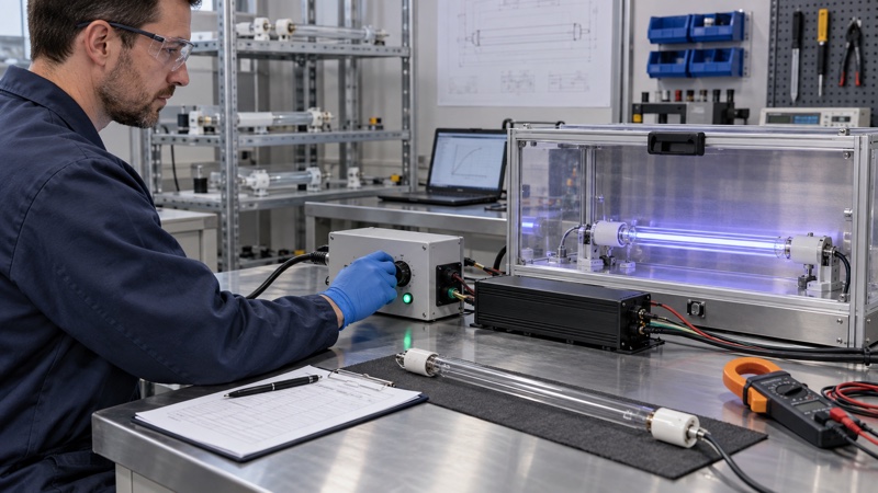
Common control interfaces to clarify
Analog control input
Some ballasts accept an analog command, such as a voltage or current signal, that represents the requested power level. The exact range, reference ground, isolation and fail-safe response must come from the ballast documentation. Do not assume that two ballasts using the same nominal signal interpret it identically.
Digital or stepped power control
Other designs use discrete inputs, serial communication or a limited set of power stages. This can simplify validation because the OEM tests a small number of defined operating points. Confirm the communication protocol, addressing, update timing and behavior after loss of control signal.
Feedback and fault outputs
A control command alone does not prove that the lamp reached the requested output. The system may also need ballast-ready, lamp-failure, overtemperature or actual-power feedback. For disinfection equipment, pair electrical status with the project’s required UV monitoring method.
Define startup before reduced-power operation
Many lamps need a specific ignition sequence and warm-up period before stable reduced-power operation. An OEM may start at full or specified power, wait for electrical and UV conditions to stabilize, and then move to the requested level. The correct sequence is model-specific.
For high-output water systems, review the amalgam UV lamp warm-up guide. It explains why flow permissives, sensor thresholds and restart behavior should be coordinated with lamp startup rather than controlled by an arbitrary timer.
Set a validated minimum power level
The lowest controller setting is not necessarily the lowest safe or useful operating point. At very low power, a lamp may become thermally unstable, produce insufficient UV output or respond inconsistently to changes in airflow or water temperature. The ballast may also have a minimum regulated load.
During development, test several power levels under the expected temperature and flow range. Record input power, lamp electrical values, UV sensor response, stabilization time and alarms. Select a minimum operating level that remains stable and satisfies the system’s treatment criteria with suitable margin.
Coordinate power control with the application
Water disinfection systems
Power control may be linked to flow, UV transmittance or a validated dose-control strategy. The reactor, quartz sleeves, sensor position and cleaning condition all affect system performance. Use the UV water sterilizer commissioning checklist to test the complete installation and its fault responses.
Air and HVAC equipment
In air systems, lamp temperature can change with fan speed and ambient conditions. If power follows airflow, validate the lamp and module at all intended fan and power combinations. BIOSUN’s UV air duct lamp selection guide covers placement, temperature and service considerations for HVAC projects.
Appliance and compact OEM modules
Compact products may have limited ventilation and shared power electronics. Check enclosure temperature, electromagnetic compatibility, connector ratings and control-board behavior at every power step. For small integrated systems, the photoplasma module guide provides additional OEM integration points.
Sample validation checklist for dimmable UV systems
Electrical tests
Confirm ignition, rated operation, minimum and maximum power, lamp current, input power, control-signal response and fault outputs. Repeat tests at the specified supply-voltage limits and after controlled power interruptions.
Thermal tests
Measure relevant lamp, ballast and enclosure temperatures at each operating point. Include low airflow, maximum water cooling and other conditions that could move the lamp away from its preferred temperature range.
Output and control tests
Map each command level to measured UV response using the system’s approved method. Check transition time, overshoot, stability and response to a missing or invalid control signal. Retain this mapping with the approved sample record described in the UV lamp sample approval guide.
Lifecycle and switching tests
Test the expected number of power changes and on-off cycles. Inspect lamp ends, connectors and ballast temperature after the cycle test. The UV lamp end-darkening guide can help service teams document electrode-area changes.
Common design mistakes to avoid
- Using an input-side household dimmer with a UV electronic ballast.
- Assuming control percentage and UV output are always linear.
- Changing ballast power without confirming the lamp’s permitted range.
- Skipping warm-up before entering reduced-power mode.
- Setting a minimum level from visual brightness instead of measured performance.
- Ignoring the fail-safe state when the control signal is lost.
RFQ information for a dimmable UV lamp project
Provide the lamp type, target power, application, expected temperature, airflow or water flow, supply voltage, desired control interface, feedback signals, switching frequency and annual quantity. If replacing an existing system, include lamp and ballast labels, connector photos and the current control diagram.
List whether the project needs a continuously variable output or only several fixed stages. Also identify the treatment or performance criterion used to approve each stage. BIOSUN can review the information through the UV lamp project inquiry page.
FAQ
Can any UVC lamp be dimmed?
No. The lamp and ballast must be designed and approved for power control. Confirm the permitted operating range for the exact combination.
Does 50 percent ballast power mean 50 percent UV output?
Not necessarily. Measure and validate the actual UV response under the intended thermal and application conditions.
Is dimming better than switching lamps on and off?
It depends on system size, load pattern, redundancy and component limits. Some equipment combines staged lamp banks with dimming inside each stage.
What happens if the control signal fails?
The required response should be defined during design. Depending on the application, the ballast or controller may move to a preset power, generate an alarm or stop treatment flow.
Develop a UV power-control solution with BIOSUN
BIOSUN supports overseas OEM buyers with UV lamp selection, electronic ballast matching, sample testing and custom control requirements. Send your target lamp power, operating environment and control interface through the contact page for a component-matching review.
Need a UV product quotation?
Send the model, drawing, application and expected quantity. BIOSUN will review the matching details and reply by email.
Send Inquiry