Oct 23, 2026
UV Electronic Ballast Range: 425 mA, 800 mA and 2100 mA Models
Compare UV electronic ballast models by 425 mA, 800 mA and 2100 mA lamp current, input power, startup method, controls and OEM installation requirements.
UV electronic ballasts supplied through BIOSUN cover several equipment needs: compact germicidal lamps, 800 mA high-output lamps, 2100 mA applications, two-lamp circuits and digitally controlled power supplies. The best starting point is the lamp’s electrical operating data, followed by the input supply, starting method, control interface and installation environment.
This article compares selected models from the available specification sheets so OEM buyers can shortlist a suitable ballast before requesting a matched lamp sample. It also explains where a similar-looking housing or a shared wattage label can hide an important difference.
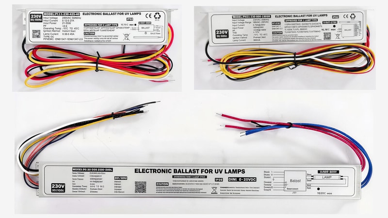
Which UV Ballast Family Fits Your Equipment?
Begin with the lamp model, nominal operating current, operating voltage and lamp count. A 425 mA lamp, an 800 mA lamp and a 2100 mA lamp require different operating conditions. The ballast also needs the correct starting circuit and approved load configuration.
Explore the BIOSUN UV electronic ballast range together with your UV germicidal lamp specification. The table below provides model examples; final selection still requires the exact lamp and approved wiring diagram.
| Model | Nominal input supply | Input power stated in sheet | Lamp-side data | Start / distinguishing feature |
|---|---|---|---|---|
| EPS5-425-40 | 230 V, 50 Hz | 45 W maximum | 0.38-0.43 A | Preheat; indicator lights and audible alarm |
| PL11-230-425-40 | 230 V, 50/60 Hz | 21-55 W at 230 V | 425 mA nominal; one lamp | Instant start; 5 V status feedback |
| PH21-230-800-150SR | 230 V, 50/60 Hz | 165 W at 230 V | 800 mA nominal; one lamp | Preheat; voltage and switching feedback |
| PH8-MLT-2100-200 | 110-240 V, 50/60 Hz | 210 W at 110 V | 2100 mA nominal; specified one- or two-lamp combinations | Preheat; wide input range |
| PL18-800-2/155 | 120/230 V, 50/60 Hz | 345 W maximum | Two lamps; 0.75-0.85 A | Instant start; lamp-status LED |
| PS80-230-2100-320L | 230 V, 50/60 Hz | 365 W at 230 V | 2100 mA nominal; one lamp | Preheat; 0-10 V dimming |
| PS90-230-AL-2320 | 230 V, 50/60 Hz | 690 W at 230 V | 1.8-3.0 A stated range; one lamp | Preheat; RS485 control and status |
Reading the table: input power is the electrical demand at the mains side, not the lamp’s UV-C output or a guarantee of compatible lamp wattage. Use the model-specific lamp list and electrical data to confirm the load.
425 mA Ballasts for Compact UV Equipment
The EPS5-425-40 and PL11-230-425-40 illustrate two different approaches within the lower-current range. The EPS5 specification gives 0.38-0.43 A lamp current, preheating for 3-5 seconds and red/green indicators with an audible alarm. Its maximum input power is 45 W, and the enclosure is specified as IP20.
The PL11 specification instead lists 425 mA nominal current, instant start and a 5 V DC/10 mA lamp-status signal. Its stated input-power range is 21-55 W at 230 V. Although both models serve lamps in a similar current family, their startup and monitoring arrangements differ.
For a compact water purifier or an appliance that cycles frequently, share the switching pattern before approving the ballast. The UV lamp preheating and startup guide explains why lamp construction and starting circuit should be evaluated together.
800 mA Ballasts for High-Output Lamp Projects
The PH21-230-800-150SR is specified for one lamp, with 800 mA nominal lamp current and a listed range of 720-880 mA. It uses preheat starting and has a nominal 230 V supply with a 198-264 V input range.
Its sheet lists IP62, a maximum case hot-spot temperature of 70 C and maximum ambient temperature of 45 C. These are separate conditions: a cool room does not guarantee that a densely packed cabinet keeps the ballast case within its limit.
For water-treatment designs needing a flow-switch input, the IPS60-MLT-800-95SK sheet describes an alternative with 110-240 V nominal input, 800 mA output, preheat starting and an audible/visual alarm. Confirm the complete model code when requesting this configuration.
When the project involves a submersible UV lamp assembly, specify the output cable and connector as part of the lamp-ballast combination. A ballast’s enclosure rating does not by itself make the power supply suitable for immersion.
2100 mA Ballasts and Controlled High-Output Systems
The PH8-MLT-2100-200 offers 110-240 V nominal input and 2100 mA nominal lamp current, with a listed 1900-2300 mA range. The specification identifies particular one-lamp and two-lamp loads. It should therefore be selected against the approved combination rather than treated as a universal two-lamp driver.
The PS80-230-2100-320L adds a different control option. Its sheet lists one lamp, 2100 mA nominal current, preheat starting, dry-contact lamp feedback and a 0-10 V DC dimming interface. Its input power is listed as 365 W at 230 V.
0 V Does Not Necessarily Mean Lamp Off
For this PS80 model, the sheet specifies 200 W at a 0 V command and 320 W at 10 V. Buyers should not assume that a zero-voltage dimming command switches the lamp off. Define a separate approved start/stop method and confirm the control behavior during commissioning.
For high-output or amalgam UV lamp applications, match the actual lamp and operating temperature before choosing the ballast. The control range must suit the lamp and validated treatment process.
Two-Lamp Ballasts Need a Defined Load and Duty Cycle
The PL18-800-2/155 is specified for two lamps and 0.75-0.85 A output current. Its sheet gives 120/230 V nominal input, a 99-264 V input range, 345 W maximum input power and IP64 protection.
The same sheet describes instant starting for applications without frequent starts. This matters for equipment with short operating cycles. A buyer should confirm the exact two-lamp arrangement, how the ballast responds if one lamp fails and whether the duty cycle matches the intended service.
For replacement equipment, provide both lamp markings, the existing ballast label and the wiring diagram. The replacement UVC lamp range can be matched more reliably when the complete circuit is known.
Choose the Control Interface Before Finalizing the Cabinet
The available documents describe analog, PWM and digital control options on different models. They are alternative interface designs, each with its own electrical requirements.
- 0-10 V: PS80-230-2100-320L lists a 0-10 V DC command at 5 mA and dry-contact lamp feedback.
- PWM: PS9-230-AL-320P lists a 1-5 kHz, 10 V PWM interface, with model-specific preheat and lamp-current settings.
- RS485: PS90-230-AL-2320 lists an RJ45 interface for start/stop, power adjustment and lamp-status feedback.
For RS485 integration, request the communication protocol, connector pinout and required settings. The connector shape alone does not establish compatibility with a controller. For general control sequencing, review the UV lamp power-control guide.
Medium-Pressure Power Supplies Are a Separate Selection
The portfolio also includes medium-pressure UV power supplies. The MPLB-1PH-A-2000 manual distinguishes 2000 W lamp power from 2100 W maximum input power and describes PWM control. The HS-EPS manual covers 1 kW, 2 kW and 3 kW models with different voltage and current limits.
These supplies should be matched using the medium-pressure lamp’s voltage, current, ignition requirements and cooling arrangement. A low-pressure ballast and a medium-pressure supply cannot be shortlisted from wattage alone. Ask for the exact input configuration and installation drawing for the intended model.
Check Mounting, Temperature and the Cable Assembly
Housing length, mounting-hole spacing, terminal access and lead arrangement can determine whether a replacement fits the cabinet. Compare the drawing as well as the electrical table before placing an order.
Output-cable limits vary by model. Specify the ballast-to-lamp distance, conductor size, connectors and routing in the quotation request. Where a document has conflicting cable-length wording, obtain a confirmed wiring specification before production approval.
Match the lamp holders and connectors to the approved base and starting circuit. Lamp-status feedback also needs to be distinguished from optical performance: the UV monitoring guide explains what electrical and intensity signals can tell the equipment controller.
Confirm Documentation for the Exact Ordering Code
Compliance evidence should match the complete model, production label and intended market. Some individual specification sheets state CE and RoHS; available certificate files also identify particular models and certificate holders. Those documents should be reviewed for the selected ordering code.
A statement that internal wiring uses UL-certified wire is not a statement that the complete ballast has product certification. Request the applicable certificate and supporting identification when the project requires them.
What to Send for a Ballast Quotation
- Lamp model, operating current, voltage, wattage and lamp count
- Input voltage, mains frequency and destination market
- Operating hours, start frequency and required startup method
- Control interface and lamp-fault feedback requirements
- Cabinet drawing, available space and ambient conditions
- Output cable length, holder type and connector photographs
- Required documentation, sample quantity and production volume
BIOSUN’s OEM and ODM service can help coordinate lamp, ballast, accessories and sample validation. Engineering approval should record the exact model and wiring revision for repeat orders.
Frequently Asked Questions
Is input power the same as lamp power?
No. Input power describes the mains-side demand, including ballast losses. Lamp electrical power and UV-C radiation output are different values.
Can two 800 mA ballasts always replace each other?
No. Lamp voltage range, starting method, lamp count, feedback, wiring and environmental limits must also match.
Does every model support dimming?
No. Dimming is model-dependent. Select an interface explicitly stated in the relevant specification and verify its range with the intended lamp.
Which model should I choose for a wet installation?
Start with the environmental requirements of the complete equipment and then select the specified enclosure, connectors and protected mounting location. The available ratings vary by model; an IP65 ballast is not an immersion-rated assembly.
Request a Matched UV Lamp and Ballast Sample
Send your lamp data, existing ballast marking and equipment conditions through the BIOSUN inquiry page. The team can narrow the current family, control option and installation arrangement before preparing a sample.
Need a UV product quotation?
Send the model, drawing, application and expected quantity. BIOSUN will review the matching details and reply by email.
Send Inquiry